

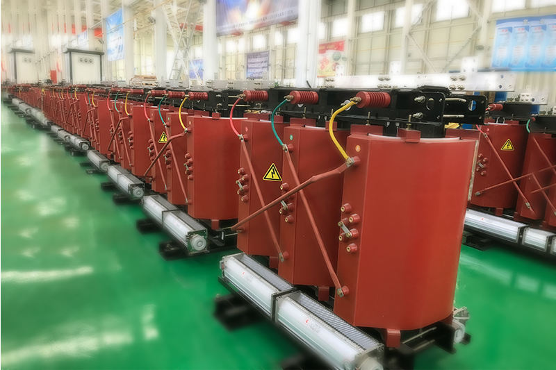
A transformer consists of an iron core (or magnetic core) and a coil. The coil has two or more windings. The winding connected to the power source is called the primary coil, and the remaining windings are called secondary coils. It can transform AC voltage, current and impedance. The core transformer is composed of a core made of soft magnetic material and two coils with different numbers of turns on the core, as shown in the figure.
Transformer principle
The core's role is to strengthen the magnetic coupling between the two coils. In order to reduce the eddy current and hysteresis loss in the iron, the iron core is formed by lamination of painted silicon steel sheets; there is no electrical connection between the two coils, and the coils are wound by insulated copper wires (or aluminum wires). One coil connected to AC power is called the primary coil (or primary coil), and the other coil connected to the electrical appliance is called the secondary coil (or secondary coil). The actual transformer is very complicated. There are unavoidable copper loss (heating of the coil resistance), iron loss (heating of the core), and magnetic leakage (air-closing magnetic induction wire). To simplify the discussion, only the ideal transformer is introduced here. The conditions for an ideal transformer to be established are: ignore the magnetic flux leakage, ignore the resistance of the primary and secondary coils, ignore the core loss, and ignore the no-load current (the current in the primary coil when the secondary coil is open). For example, when the power transformer is running at full load (the output power of the secondary coil) is close to the ideal transformer situation.
Transformers are stationary electrical appliances made using the principle of electromagnetic induction. When the primary coil of the transformer is connected to an AC power source, an alternating magnetic flux is generated in the core, and the alternating magnetic field is generally expressed by φ. Φ in the primary and secondary coils is the same, φ is also a simple harmonic function, and the table is φ = φmsinωt. According to Faraday's law of electromagnetic induction, the induced electromotive forces in the primary and secondary coils are e1 = -N1dφ / dt and e2 = -N2dφ / dt. In the formula, N1 and N2 are the number of turns of the primary and secondary coils. It can be seen from the figure that U1 = -e1 and U2 = e2 (the physical quantity of the original coil is represented by the subscript 1 and the physical quantity of the secondary coil is represented by the subscript 2). Let k = N1 / N2, called the transformer's ratio. According to the above formula, U1 / U2 = -N1 / N2 = -k, that is, the ratio of the effective value of the transformer primary and secondary coil voltages is equal to the turns ratio and the phase difference between the primary and secondary coil voltages is π.
Which in turn leads to:
U1 / U2 = N1 / N2
In the case where the no-load current can be ignored, there is I1 / I2 = -N2 / N1, that is, the magnitude of the effective value of the primary and secondary coil currents is inversely proportional to their number of turns, and the phase difference is π.
Further available
I1 / I2 = N2 / N1
The power of an ideal transformer's primary and secondary coils is equal to P1 = P2. This shows that the ideal transformer itself has no power loss. The actual transformer always has losses, and its efficiency is η = P2 / P1. The efficiency of power transformers is very high, reaching over 90%.

 power generation")


Leave A Comment